Configuration
This product can be freely customized through the web configuration tool (https://config.parkstool.com). To change functionality, you must use the web configuration tool to modify settings.
Warning
MIDI controller functionality (playing, CC/Note transmission, etc.) works normally on all platforms. However, configuration changes via the Web Configuration Tool are PC only.
iOS / iPadOS: Apple WebKit does not support the Web MIDI API, so the Web Configuration Tool is unavailable on all browsers.
For configuration changes, please use a PC (Windows or Mac) with Chrome or Edge browser.
Interface Overview
Note
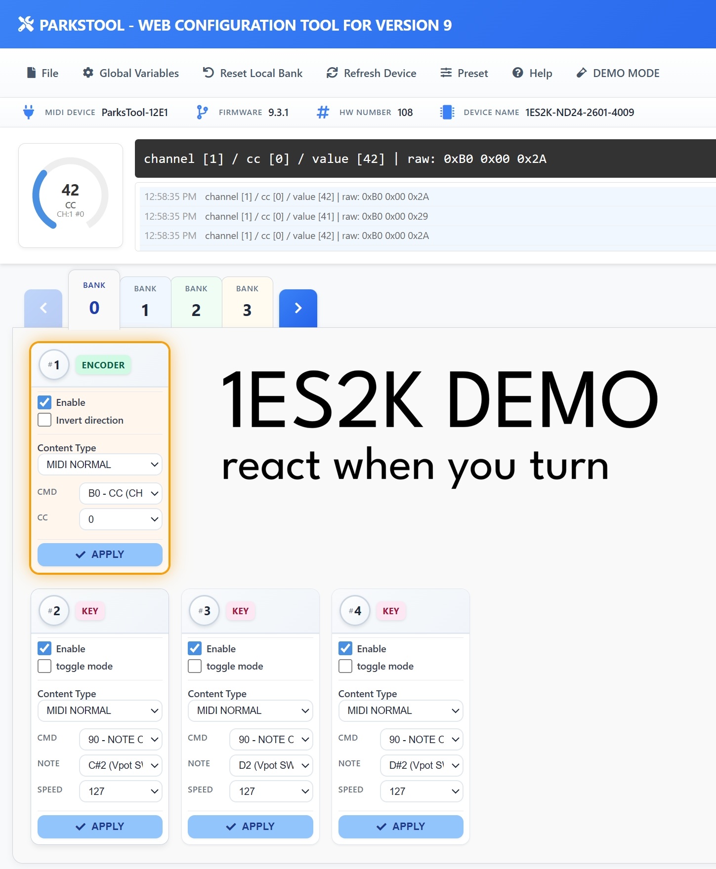
The screenshot above is an example based on the 1ES2K. The number and type of controls displayed (encoders, keys, faders, potentiometers) may vary depending on your product.
The web configuration tool consists of the following main areas:
Top Menu Bar
File — Save/load configuration files
Global Variables — Global settings including number of Banks and Bank Looping
Reset Local Bank — Reset the current Bank settings
Refresh Device — Reconnect the connected device
Preset — Load a pre-saved preset
Help — Help
DEMO MODE — Lets you explore the interface without a connected device. Useful for previewing features before purchase or practising your configuration.
Device Info Bar
Information about the connected device is displayed in a single line:
MIDI DEVICE — The MIDI device name recognised by your computer (e.g.
ParksTool-12E1)FIRMWARE — The current firmware version (e.g.
9.3.1)HW NUMBER — Hardware serial number
DEVICE NAME — Product SKU name (e.g.
1ES2K-ND24-2601-4009)
MIDI Monitor
MIDI messages sent from the device are displayed in real time. The format is as follows:
channel [1] / cc [0] / value [42] | raw: 0xB0 0x00 0x2A
channel— MIDI channel number (1–16)cc— CC number (0–127)value— Current value (0–127)raw— Raw MIDI bytes transmitted (hexadecimal)
The log area records recent messages with timestamps, and the circular gauge on the left visually displays the current value, MIDI type, channel, and CC number.
Bank Tabs
Banks from 0 to N are displayed as tabs. Click a tab or use the arrow buttons to switch Banks. The tab highlighted in blue is the Bank currently being edited.
Control Cards
Each control is displayed as a card. The top of each card shows the control number (#1, #2, …) and a type badge (ENCODER, KEY, FADER, POTENTIOMETER, etc.).
Settings available on each card:
Enable — Whether the control is active
Invert direction — Encoders, potentiometers, and faders only. Reverses the value direction.
Toggle mode — Keys only. Alternates between On and Off with each press.
Content Type — Select the type of MIDI message (MIDI NORMAL, PITCHBEND, etc.)
After making changes, you must press the APPLY button to save them to the device.
Tip
Orange border: The card of the control currently being physically operated is highlighted with an orange border in real time. When you turn a knob or press a key, the corresponding card is highlighted, making it easy to see which control you are using — especially helpful during configuration.
🔁 Additional Bank Information
By default, 2 Banks are provided, and the number of Banks can be changed in the Global Variables tab of the Web Configuration Tool.
Encoders with physical detents are recommended for Bank switching.
When Bank Looping is enabled, it cycles from the last Bank back to the first Bank. Useful for single button devices.
Each Bank requires configuration before use.
Potentiometer products can also change banks. It is recommended to set other banks as bank features. Otherwise, after bank changes, that element will no longer function as bank change and will become general midi mode.Potentiometer products can also change banks. It is recommended to set other banks as bank features as well. Otherwise, after the bank changes, that element will no longer operate as bank change and will become general MIDI mode.
🔢 Changing USB PID (when using two devices on the same PC)
To connect two or more ParksTool devices of the same model to one PC at the same time, each device’s USB PID (product identifier) must be different. Otherwise the PC sees them as the same device — one may fail to be recognised, or inputs may get mixed up.
How to change it:
Connect only the device you want to change to the PC, then open the Web Configuration Tool.
Open Global Variables in the top menu bar.
Pick a number to use under the USB PID item.
Once applied, the device reconnects automatically and is recognised with the new number.
Unplug the first device, connect the second, and assign a different number using the same procedure.
Note
Each ParksTool product offers 15 available numbers. When using two or more, just make sure each is set to a different number.
This feature is only available on firmware 9.3.5 or later.
🔧 When the product name is shown incorrectly (Setting the Hardware Number)
Symptom
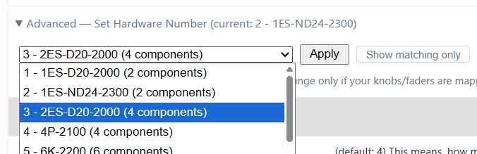
After a firmware update, the product name shown in the device information may differ from the product you actually bought. For example, a two-encoder product may be recognized under a completely different name (e.g. ``1ES-ND24-2300``). This mostly happens on early units.
Cause
The device stores a “product profile number” that tells it which product it is. On older units this number can be out of sync with the actual product. The hardware itself is fine — once the correct profile is set again, the name and the knob/key mapping are restored to match the product.
How to fix it
Connect the device by USB and open the Web Configuration Tool.
Open Global Variables in the top menu bar.
Under Device information, expand Advanced — Set Hardware Number. It shows the currently detected number and name.
By default, only products with the same number of components as your unit are shown. If your actual product is not in the list, click the Show all profiles button to reveal the full list.
Choose the number that matches your actual product, click Apply, and confirm. The setting is saved to the device and persists across power cycles.
Finally, run Auto Update once in the ParksTool Uploader. It installs the firmware that matches the product, and the name and mappings return to normal.
Note
Most users never need this. Use it only when the displayed product name does not match your actual product, or the knobs/faders appear mapped incorrectly. If you are not sure which number to choose, please contact ParksTool.
Mapping and User Settings
✨ Basic Mapping Features
Keys, knobs, media keys, etc. can be freely mapped through the Web Configuration Tool.
When the product is connected and the configuration page is opened in a web browser, it is automatically recognized.
Per-Component Additional Settings
Each component (PEK) supports the following settings in addition to Content Type.
Invert direction: Reverses the value direction for encoders, potentiometers, and faders. Does not apply to keys.
Toggle mode: Key only. When enabled, each key press alternates between On and Off. (Not shown in BANK FEATURE mode.)
REPEAT: Available in Keyboard / Consumer Control / Mouse modes. Sets how many times the input is repeatedly transmitted when a key is pressed once. For example, setting it to 5 will send the key input 5 times with a single press. Configurable from 1 to 60.